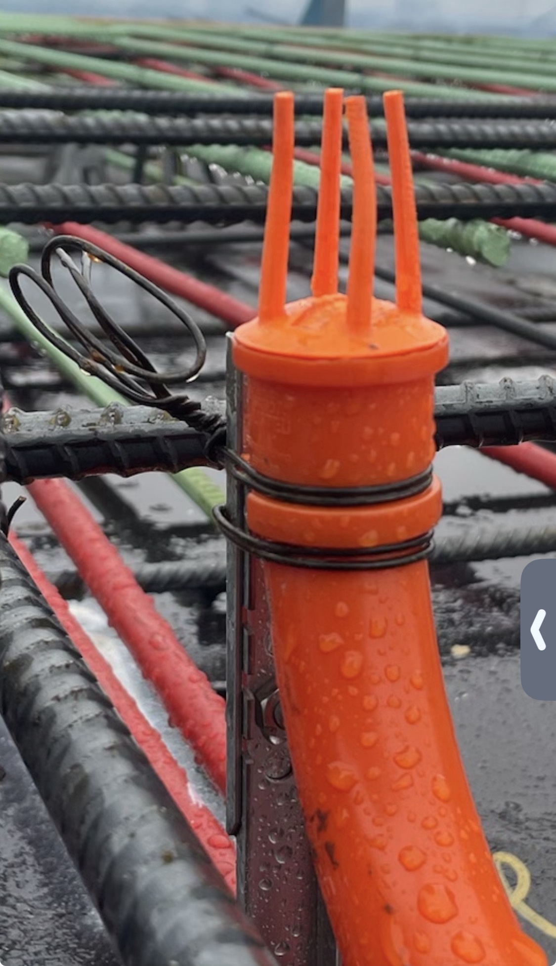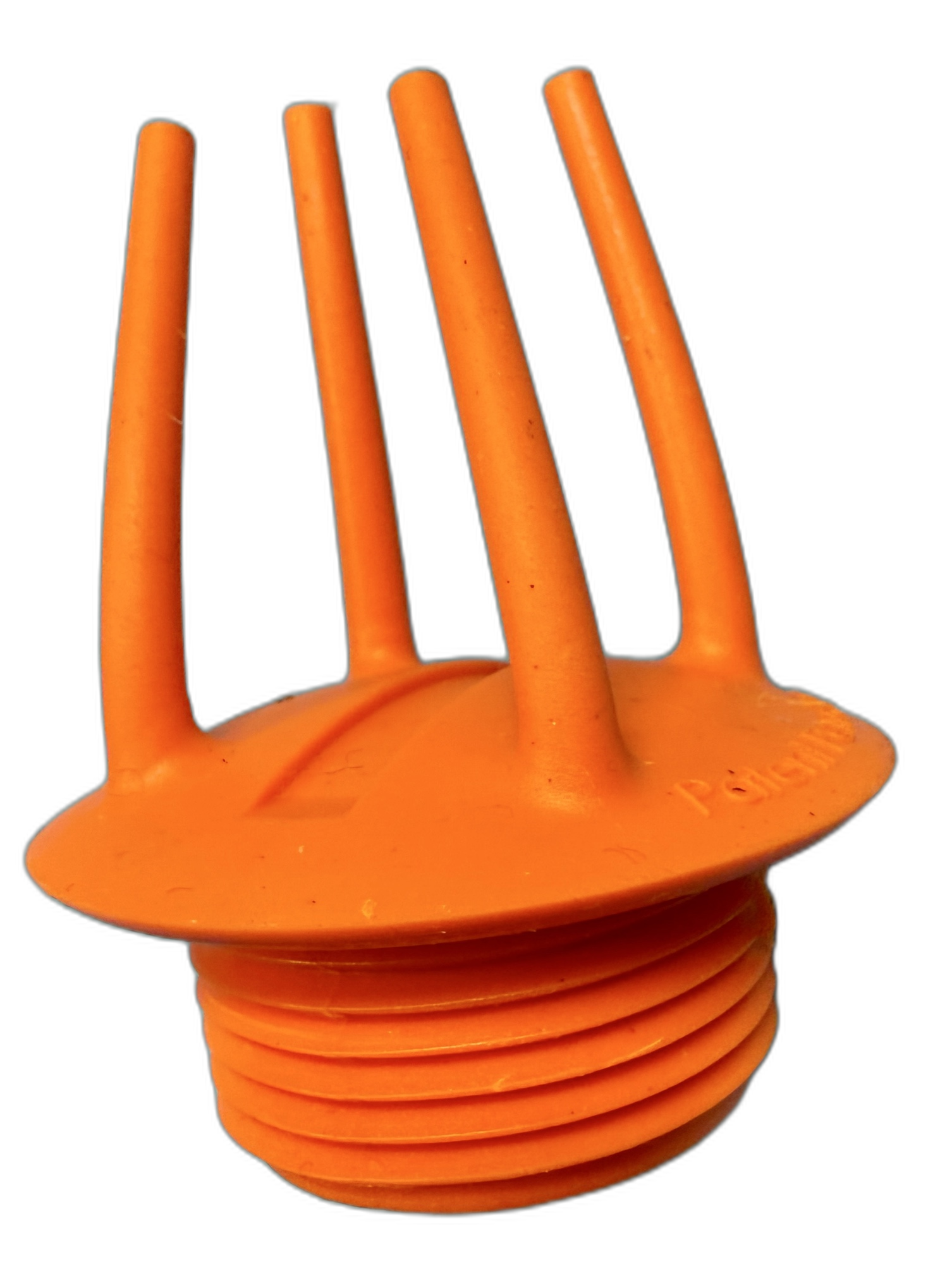
Every Stub-EASE II™ kit ships from the manufacturer with the cap already threaded on. The only prefabrication required is setting the assembly to your exact slab elevation before it reaches the deck. Once it arrives, the field crew aligns the layout targets, screws it down in three locations, and walks away. This page shows you exactly how it works — and exactly how it comes out.
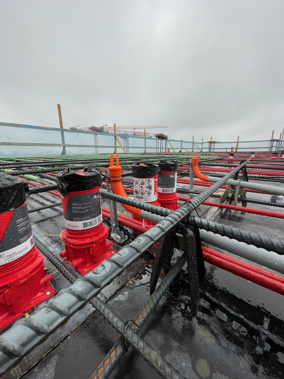
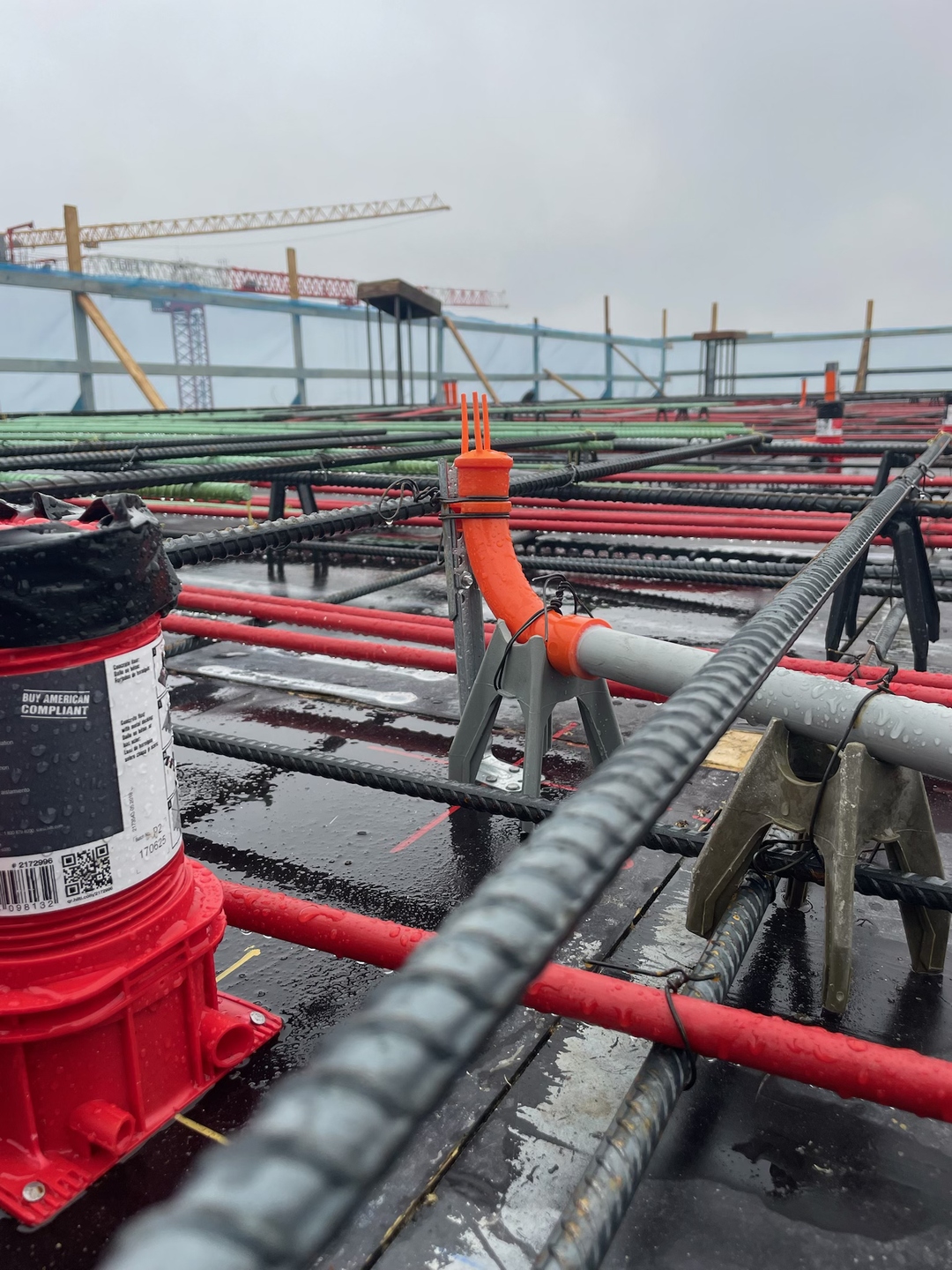
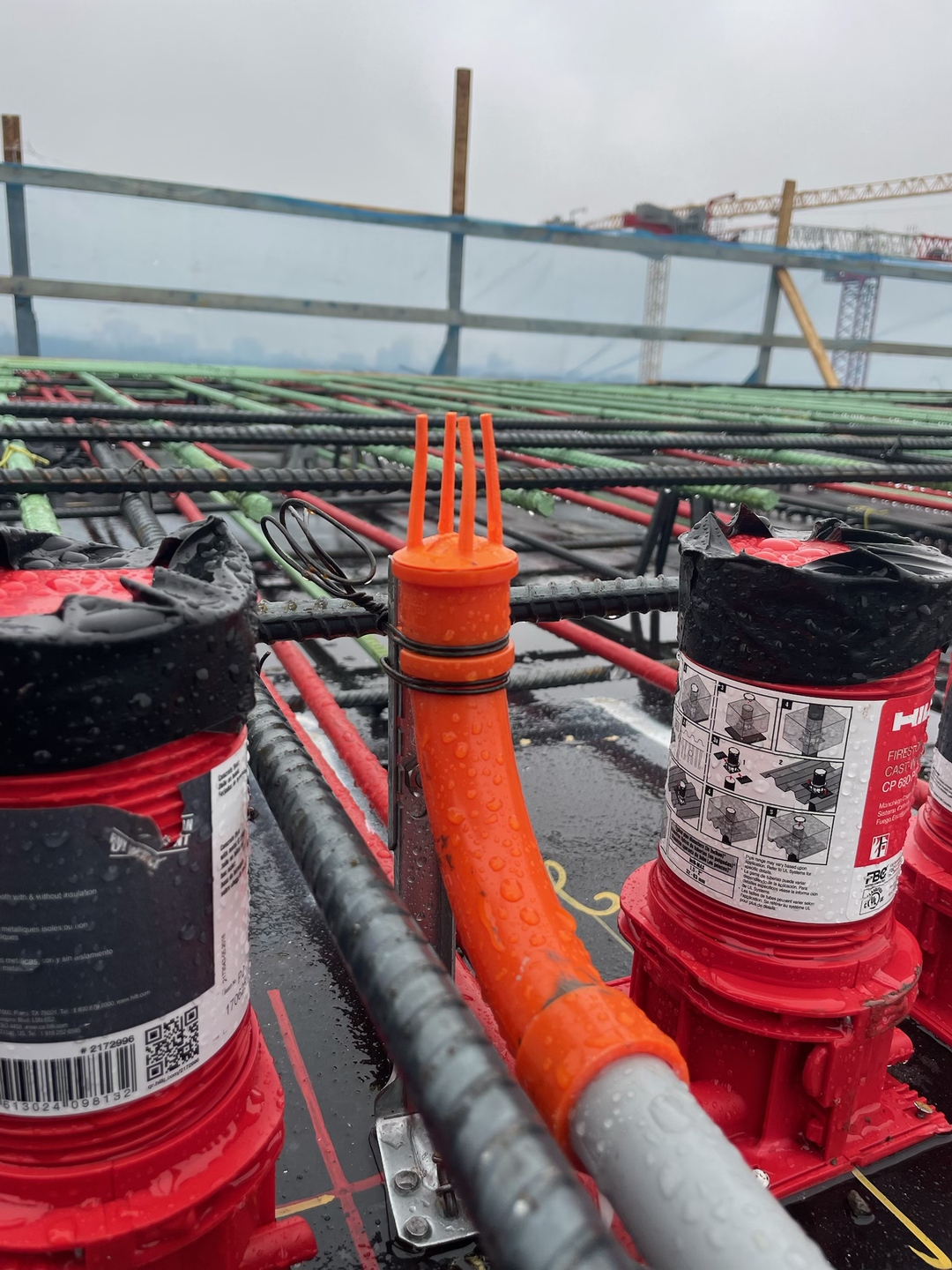
The Stub-EASE II™ system was engineered so all assembly happens before the kit reaches the deck — the field crew has one step. No special tools. No complex assembly on the deck. Align, screw down, walk away.
Every Stub-EASE II™ (convex cap with talons) kit ships from the manufacturer with the Stub-EASE II™ cap already threaded onto the Bend-EASE™ elbow. The only prefabrication required before delivery to the deck is setting the assembly to the exact slab elevation. That step must be completed before the kit reaches the deck — where time is critical and no assembly work belongs.
Kits must be pre-ordered with either an 8" or 12" Stand-EASE™ support. If the installed elevation varies from these two set points, measure the exact variance from deck height and cut the Stand-EASE™ support from the top down by that amount. In this way, the click-lock always aligns with the top detent on the Stand-EASE™. Once cut to the correct elevation, insert the Bend-EASE™ elbow into the Stand-EASE™ support and click it into the detent. The assembly is now set to your exact slab depth and ready to secure.
Using your choice of doubled tie wire or stainless steel straps, bond the Bend-EASE™ to the Stand-EASE™ support at this time. The photos below show tie wire as a reference for method — this is the standard practice used throughout the rebar deck. Stainless steel straps are an alternate means and methods. Once secured, the kit is ready to ship to the deck.
Suggested alternate securing method: stainless steel straps (personal research recommended).
Once deck layout is done, the field crew aligns the trade-size markings molded into the Stand-EASE™ pedestal with the deck layout — 3/4" center line or 1" center line. Fasten the pedestal in three locations. The back leg is built into the Stand-EASE™ for additional stability; no extra hardware needed.
That is the installation. One step. Walk away and come back when you are framing the walls. A full installation video is being produced and will be available here.
After the concrete has cured: match the spade bit to your trade size — 3/4" pipe takes a 3/4" spade bit, 1" pipe takes a 1" spade bit. Insert the tip into the engineered guide strip depressed into the center of the convex cap. Run the impact driver in reverse. The cap threads itself out cleanly in seconds.
What is left behind is a conduit interior that is completely clean and ready for wire pull — on every stub-up, every floor. No prying, no cutting, no chipping, no rework.
NEC 300.15(F) / 300.17(F) requires that a fitting or connector be used wherever a conductor or cable exits a raceway. In concrete construction, that requirement becomes critical at exactly the point where horizontal conduit turns vertical and stubs up through the slab.
This is also the point where jobs frequently need to transition from metallic conduit embedded in the structure to PVC conduit above it. NEC 300.15(F) permits that metallic-to-PVC transition when an approved fitting is used.
The Bend-EASE™ elbow was designed and tested to meet UL specifications for use as a transition fitting between metallic and PVC conduit systems in concrete construction per NEC 300.15(F) (2023 NEC) / NEC 300.17(F) (2026 NEC). That means the transition point in the Stub-EASE II™ system is not an afterthought — it is the reason the elbow exists.
Code-Compliant with Both Metallic and PVC Raceways
Whether the below-slab conduit run is metallic (EMT or RMC) or PVC, the Bend-EASE™ elbow is the approved transition fitting under NEC 300.15(F) / 300.17(F) for either path. In a metallic run, the conduit itself is the equipment grounding conductor — the Bend-EASE™ elbow embedded in concrete adds no grounding obligation. In a PVC run, an equipment grounding conductor inside the conduit was already required before the elbow is even in the picture. Either way, the Bend-EASE™ elbow adds zero grounding burden. One product. Any raceway. No exceptions, no workarounds.
Raceway in the Slab Determines the Adapter Requirement
The type of conduit run in the slab — not what continues above it — drives whether transition adapters are needed. If the below-slab run is metallic (EMT or RMC), PVC-to-EMT adapters are placed on the horizontal or in-slab portion of the conduit where it connects to the Bend-EASE™ elbow. If the below-slab run is PVC, no adapters are needed below the slab — the elbow glues directly. Above the slab, the contractor continues with either metallic or PVC as the job dictates. Two field-proven methods are available when continuing metallic above the slab, both compliant with NEC 300.15(F) (2023 NEC) / NEC 300.17(F) (2026 NEC):
Glues directly onto the Bend-EASE™ elbow. Manufactured to meet or exceed UL 651 — same standard as the elbow itself.
3/4" → 75PVC/EMT | 1" → 100PVC/EMTGlue a PVC female adapter onto the elbow, thread a standard EMT connector into the female threads. Standard parts, widely available at any electrical supply house.
Both methods meet NEC requirements provided no conductors are spliced or terminated inside the fitting.
"A fitting or connector shall be used wherever a conductor or cable exits a raceway..." — applied at the metallic-to-PVC transition point in concrete construction.
Unprotected stub-ups sit directly in the path of power-trowel blades during slab finishing. Industry data shows 30–40% of exposed conduit is bent, crushed, or destroyed during this single finishing pass — conduit that then has to be cut out, re-run, and re-pulled.
Every open stub-up left standing on working walking surfaces is a trip hazard for every trade that crosses that floor afterward — framers, mechanical, drywall crews, inspectors. It only takes one fall to turn a punch-list item into a lawsuit.
From horizontal run to clean, wire-ready conduit — Stub-EASE II™ installed, poured over, and extracted in the field.
Extraction demo — impact driver in reverse, spade bit matched to trade size. The full assembly pulls clean in seconds.
Cap flexes under trowel — talons spring back
Walk-behind trowel pass — cap survives
Hand trowel pass — talons visible after finish
Riding trowel — Schaumburg jobsite
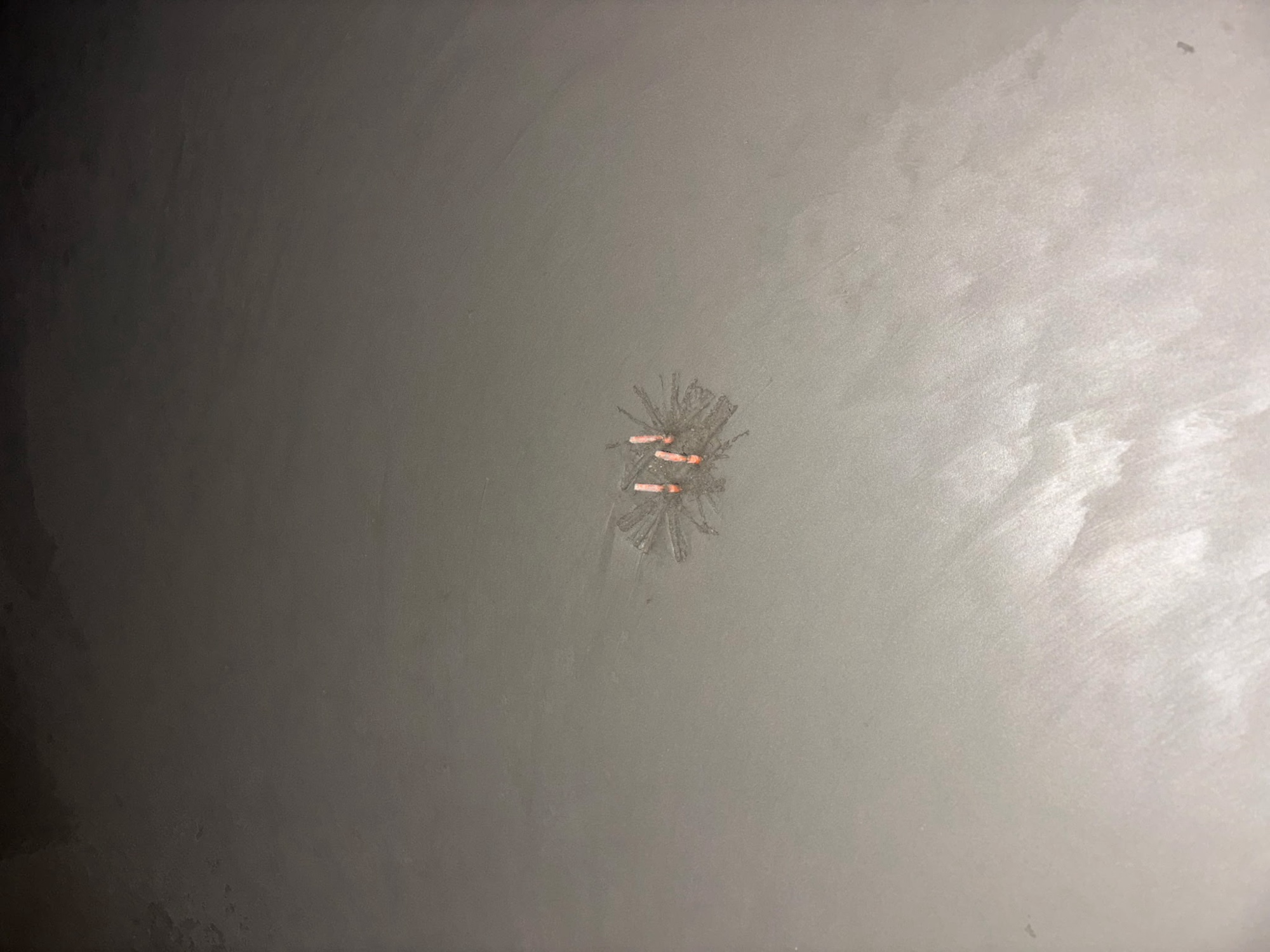
Orange talons visible at grade — post-trowel finish
Full system assembly illustrated in cross-section — from horizontal conduit run through the deck to wire-pull-ready sleeve above slab.
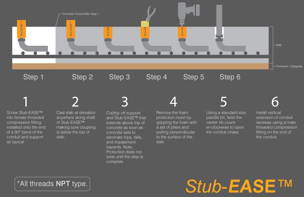
All threads NPT type. Extraction uses a standard spade bit matched to trade size — 3/4" pipe uses 3/4" bit, 1" pipe uses 1" bit. Impact driver in reverse.
Order product, or reach out directly to Jeff Krause at CSUE Technologies.